|
|
Last update: 27/05/01 0.31.00 |
Hallicrafters SX-28 Superskyrider – Detector page
This page is
dedicated to describe and understanding the SX-28's detector and related circuits.
In fact the detector stage comprises the detector itself, the developing of AVC
potential for the first AVC and an AF-Noise limiter.
Having a look at the
original diagram from Hallicrafters, it was not so clear to me what kind of
circuit it is. So I have re-drawn it in a different and more understandable
way.
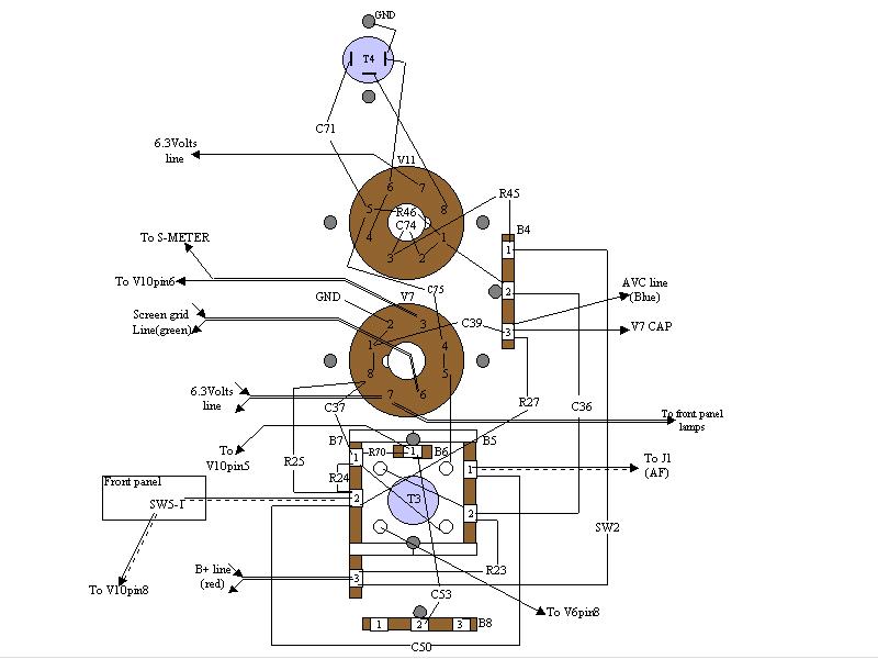
This is the original Hallicrafters diagram .I went through this intermediate redrawing before understanding the
correct way to look at it. This is the chassis diagram.
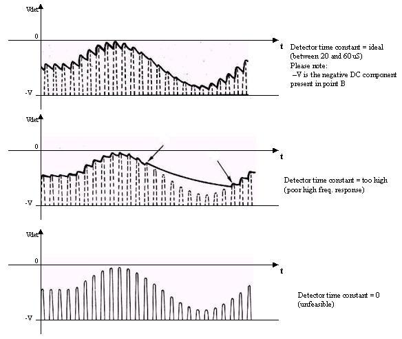
The AM detection
is in the usual configuration with the diode section of V7 (6B8). The network
made by C37, R24 and R25 is the filter removing the IF out of the detected
signal. The time constant of this filter is about 30 uS, more than adequate for
a good audio response with a 455KHz IF. Please note that the full detected
signal and a negative DC component are present at point B as well as in
point A (even if slightly reduced). See pic. The DC
component is proportional to the amplitude of the carrier (IF here!). The signal is taken from point A and sent to
the AF amplifier by mean of C50 useful to get rid of the DC component. The AVC
control signal is developed and smoothed by R27/C39 with a time constant of
about 10mS. The AVC line is shunted to ground in AVC-OFF and BFO-ON positions
of SW1. The AVC potential also drives the control grid of a DC amplifier
(V7/R28/R30) used to drive the S-Meter.
The ANL
section (V10) follows the shunt diode switching design. This kind of noise
limiter renders the receiver inoperative for the duration of noise pulses. In
fact:
Under this
condition the diode is always slightly back-biased, and thus not conducting. It
is back-biased enough for the plate not to become more positive than the
cathode even when the normal LF signal reaches its maximums. In presence of a
sharp noise spike (negative), points B and A suddenly follow the spike, but the
plate of V10 remains at the same potential delayed by the RC R70/C53. That
means that until C53 allows for the plate to realign to point B the diode
conducts shunting point A to ground through C53 itself.
|
|
Last update: 27/05/01 0.31.00 |