|
|
Last update: 05/01/02
15.28.00 |
Hallicrafters
SX-28
restoration log
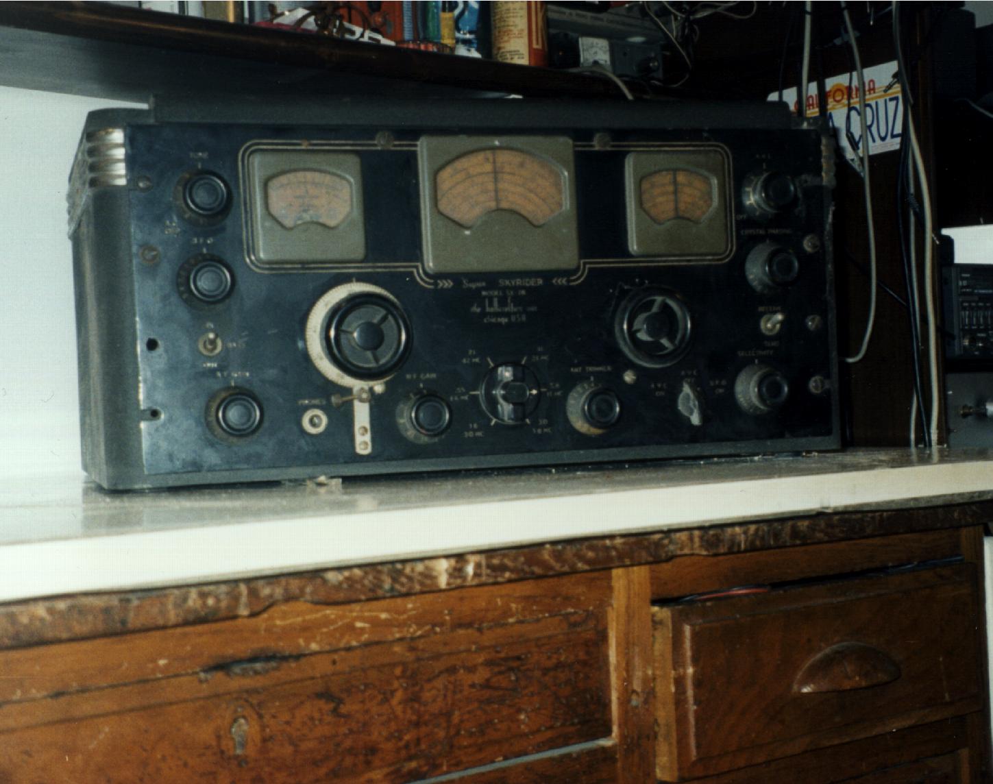
17-4-99
This is the kick off day. I've taken the pictures in the cellar using my web cam, and brought the radio upstairs in my lab. Taken some pictures again just to remember as it wasģ
Got the rig out of the cabinet,
First cleanup with vacuum cleaner, a brush and a dry damp cloth and with the help of an compressed air can.
A lot of dirt but signs in the front panel are all readable. S-meter needle is positioned at the end-of-scale on the right: it seems normal. All commands seem to mechanically work well but the "crystal phasing" whose shaft is definitively too loose. Turning the main tuning knobs the dials move accordingly, but the left one some time is loose. The AF Gain rotates indefinitively and "sounds" suspect. All knobs are in place and are original.
Removed all knobs (no problems). Knobs are now in a bag with a note about their original position.
The main transformer has a big beautiful "h" on
it. It is the Hallicrafters logo: it is original!
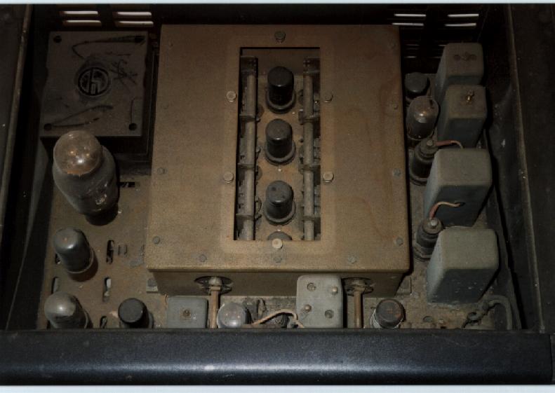
The RF box is open on top: the removable plate is missing but fortunately all
related thumbscrews are in place. Tuning gear partially works but a metal wire
is floating around. The chassis is brown in color and covered by a film of
brown crud. It passed the magneto-test so it is a steel chassis. Crystal
phasing shaft broken at the junction point. All tubes were in place. Tubes
removed and cleaned with a dry cloth only. Entries created in a tubes sheet
IÆve prepared (Excel). All tubes have been stored apart in separate plastic
bags with extensive description written on them (ID, what it should be, what it
is, socket it was removed from,...).. Some of them have signs not corresponding
with Halli's schematics. A strong compatibility and functionality check is
needed.
BFO's shaft is really loose: it seems to be due to a mechanical problem in the
variable cap ..
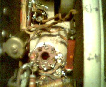
Visual analysis downside (Chassis image1, image2 ¢ Warning: 1,2MB each!)
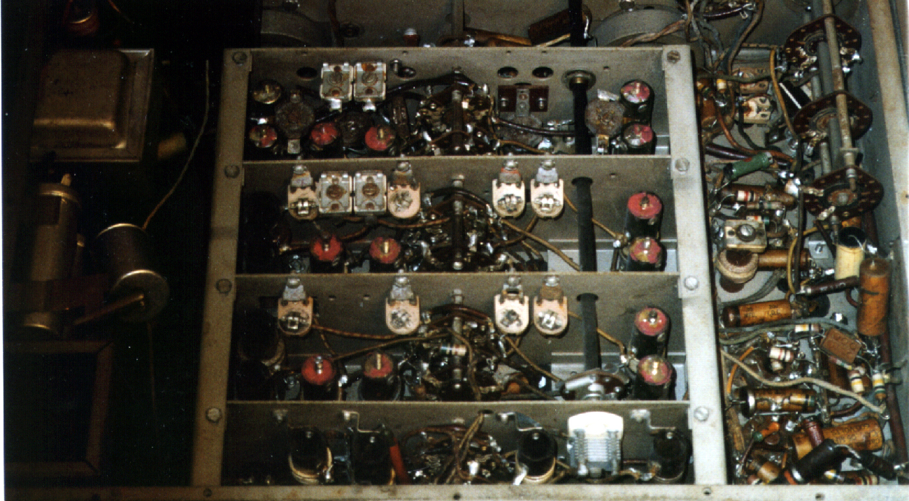
Some of the caps were already replaced by previous owners.
Wiring seem partially damaged and in some point not original. Band switch
appears in good conditions even if some contacts seem heavily oxidized. All tuning
trims in sight look as moved - the red fixing painting on them is not intact.
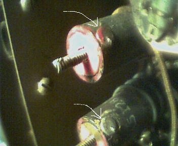
Many have the coil's screw cut broken, one has a little bolt soldered on top -
this does not look to be an original arrangement.. sgrunt!Ā Found cold Solderings of coil springs:
springs move with coil rotation. The rig has already been aligned by somebody
else (Who? Where? Why? How?).
Selectivity switch is almost wired with "modern" wires (plastic)
coming out of T2: evidence of tampering with.
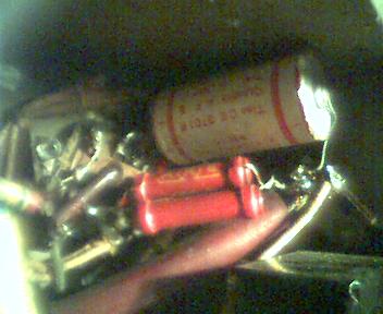
The power supply electrolytics not original: Magneti Marelli 2x(16+16uF 525Vp). They look good.
This radio is probably good for parting it out. Butģ.. I decided to continue.
Go to the top of this page | Back to the Sx-28 page
24/4/1999
The chassis is very large and complex. To keep my bearings within it, I divided it into ōzonesö, marked them on the steel and taken at least one picture for each of them. The quality is not so good due to my web cam being too raw..(.. cheap..)!
Started working in the power supply and LF amplifier areas. Intensive components identification and wiring understanding. All components have been identified and recorded on the RDD (with some additional picture of the original wiring).
Go to the top of this page | Back to the Sx-28 page
14/5/1999
After a lot of readings on the net and some old books, I am back to the radio.
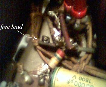
Started working on power supply. Removed CH1, electrolytics and T8. Wiring check; SURPRISE:
R43 e C76 are missing; there is an empty lead
in z20a that is probably where they were connected to.
C47 missing; Found R42
modified by a parallel of two 450 ohms and wired in ōna’f " way;
CH1 successfully passed continuity tests and shows 290 ohms d.c. resistance as per HalliÆs part list.
T8 (audio choke) successfully passed continuity tests but it has spoilt leads. Ohm test NON PASSED: measured value are far away from specs. For sure this transformer is not original. Some action is needed.
T7 (power) windings successfully passed the continuity test. Warm test passed (bulb VARIAC used) ; all voltages within limits; insulations OK.
Go to the top of this page | Back to the Sx-28 page
22/5/1999
I have been to a local hamfest and I've bought a new digital multimeter able to measure capacity too.
Go to the top of this page | Back to the Sx-28 page
29/5/1999
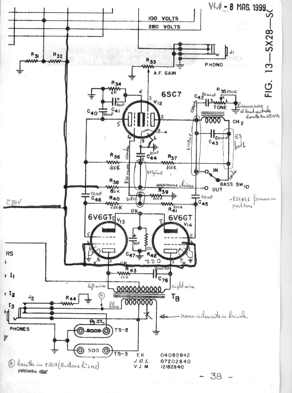
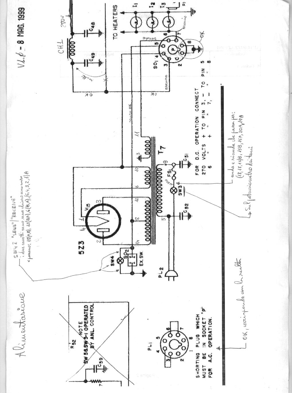
Started working on the power supply and the LF amplifier. Involved tubes are v15 (rect.),v14,v13(final PP) and v12(pre&inverter).
Resistor are almost all out of value: variances grater than +20%; some more than 50% . All tubular paper caps look very bad. To remove some components (resistors and tubular caps). I had to remove others as well (e.g. mica caps) that are not necessarily badģ.
The decision is taken to rebuild the LF amplifier from
scratch.
All components are now identified and IÆve taken some additional picture.
This
is a snapshot of my component database. Note the "remove sequence
number": it represents the order by which IÆve removed the components ¢ to
be used as a guideline when reinstalling new components. Wiring check against
weak insulation. These are the LF-amp
and power
supply diagrams I used working at restore time.
Intensive cleaning of tubes sockets by mean of a teeth brush, water and a
little of alcohol (not so effective..). I also removed and cleaned those "lead arrays" (I donÆt know the correct
English term for them) so common in vintage electronics.
Go to the top of this page | Back to the Sx-28 page
10/6/1999
A decision has been taken not to maintain the original appearance for LF-amplifier (new components will be in sight under the chassis - horror for somebody, I know!).
A couple of non standard value caps recreated with pairs series. Non standard resistors values like 200K and 250K got by measuring actual value of some NOS resistors I have in my sliders since a long time (e.g. an old 220Kohms resistor low in value is used to replace a 200Kohm resistor).
Each component back to its original position. The sequence
numbers and the pictures I 've taken before dismounting saved me a lot of time.
Next step will be to reconnect the power supply, disconnect B+ from the other
circuits, fire up the LF amplifier and test it.
Top of this page | Back to the Sx-28 Home
| Top of this page | Back to the Sx-28 Home |
Last update: 05/01/02 15.28.00 |
|
|
|
||
July 1999
I have sent all the tubes to my old friend Mario (IK1HXN) for testing. He has a friend owning a tube tester.
Looked for and found a company specialized in rewinding transformers. I have given them the T8 specs and they have provided me a new output transformer for 20$.
September 1999
The tubes came back to me with the test results: they are almost all bad. This is the tube sheet with the tests results:
|
ID |
required model |
Function |
found inside |
is it pin2pin compatible? |
Status Sep 99 |
|
V1 |
6AB7 (1853) |
1st RF Amplifier |
6AB7 (1853) |
Y |
OK |
|
V2 |
6SK7 |
2nd RF Amplifier |
6AC7 |
Y With better pendenza |
OK But Very low |
|
V3 |
6SA7 |
Mixer |
VT-150 (=6SA7) |
Y |
OK minimum |
|
V4 |
6SA7 |
HF Oscillator |
6SA7 |
Y |
OK |
|
V5 |
6L7 |
1st IF Amplifier Noise Limiter |
VT-87 (=6L7) |
Y |
OK minimum |
|
V6 |
6SK7 |
2nd IF Amplifier |
6AC7 |
Y With better pendenza |
OK But Very low |
|
V7 |
6B8 |
2nd Detector S-meter driver |
VT-93 (=6B8) |
Y |
Inefficient |
|
V8 |
6B8 |
AVC Amplifier |
6B8 |
Y |
Inefficient |
|
V9 |
6AB7 (1853) |
Noise Amplifier |
6SK7 GT |
Y But different xx pendenzaĀ xxx Try to use |
OK Minimum |
|
V10 |
6H6 |
Noise rectifier |
6H6 |
Y |
OK But Very low |
|
V11 |
6J5 |
Beat Frequency Oscillator |
6SN7 GT |
N |
OK minimum |
|
V12 |
6SC7 |
1st Audio Amplifier |
6SC7 |
Y |
OK But Very low |
|
V13 |
6V6 GT |
Push-pull Audio Amplifier |
6V6 GT |
Y |
OK |
|
V14 |
6V6 GT |
Push-pull Audio Amplifier |
6V6 GT |
Y |
OK minimum |
|
V15 |
5Z3 |
rectifier |
no writing |
? |
OK |
|
?? |
6H6 |
Found inside the rig |
No writing |
Y |
OK minimum |
So I have put an order to ESCO elettronica (TODI -PG Italy) for the following:
2x 6B8, 1x 6J5, 1x 6SC7, 2x 6V6GT
Go to the top of this page | Back to the Sx-28 page
November 1999
Received the ordered tubes and , surprise!!! 6B8, 6J5, 6SC7 are glass, while the ones that were in the rig were all metal.
Raised a question to the BA community (look for "glass Vs. metal tubes" on rec.radio.boatanchors)
December 1999
Bought a Tektronix 475 oscilloscope and a National function generator VP-7402A.
Worked a lot on building up this site.
Go to the top of this page | Back to the Sx-28 page
15-01-2000
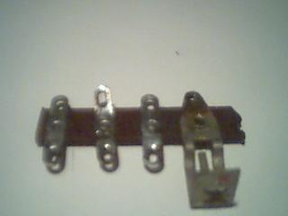
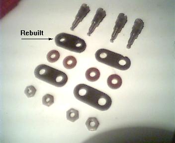
Restored the ST-2 and ST-3 Bakelite terminal leads installed on the back of Chassis for speaker connections (500ohms and 5000 ohms). One of the Bakelite insulator was missing and has been reconstructed starting from the plastic battery cover of a broken toy (it was a cellular phone dummy). These are all the pieces just before remounting them. The two connectors are now in parallel with the same output impedance=8ohm. The phone jack was also restored (some cleaning and testing) and connected to the 8ohm winding of the output choke. All these connections are not original.
Go to the top of this page | Back to the Sx-28 page
20-01-2000
The entire power supply has been rewired; filter caps mounted on the original clips. Metallic cans connected via a single wire to the chassis (it is a not original arrangement ¢ see discussion "help on some SX-28 wiring" on rec.radio.boatanchors).
Go to the top of this page | Back to the Sx-28 page
14-02-2000
Everything is ready to fire up for the first time. Done using my bulb variac. Once reached full throttle the LF amplifier is still silent.
Measured some voltage around ģ seem normal, but the grid of the first section of the 6SC7 tube seems floating. I now remember that R33 (500Kohm/log variable resistor) , the AF Gain regulator, was tricky during the first glance I had to the rig. Measured with my VOM: the central lead resulted open. I have open it for inspection and found it devastated inside. Found a replacement.
Turned-on againģ. IT WORKS!! The loudspeaker is emitting the characteristic hum when touching the input line from the PHONO jack with my fingers, very low white noise and no hum otherwise.
Connected the phonesÆ output of my Kenwood TS-430 into the SX-28ÆsĀ phono jack, and I was able to ear quite a good sound; butģ..
The 6V6GT were getting hotter and hotter, until reached a temperature that sounded not normal to me. Better investigating with the signal generator and the oscilloscope, I discovered a very low output level and high distortion (upper wave not equal to the lower one..). The output signal levels of the 6SC7 were in good shape, in opposite phase but of different levels (30Vpp of difference).
Go to the top of this page | Back to the Sx-28 page
20-02-2000
During further checks I realized that all the NOS resistors I have mounted on 10/6/99 have gone completely out of value - even 60-70%. That day it was a very bad idea to use those NOS resistors! I have 30 of them so I made a test: I have measured the value of one of them as taken out of my sliders; it measured 227Kohms. Than I simulated soldering it warming it up with my iron. When checked it again it measured 378Kohm, even after getting cool!!!! I junked all of them and I had some hard time in replacing them in the rig with new stuff. Here is how they look like - if you see any of them stay apart!!
After the work was done, almost nothing changed in the amplifier behavior - the 6V6 are really to hot, and I cannot figure out why. I getting more and more frustratedģ
Go to the top of this page | Back to the Sx-28 page
6-3-2000
After days of checks, I finally discovered one mistake: I have mounted a 22ohms resistor for R42 instead of 220 ohms. To be in a hurry is always a bad approach! With a 22 ohms bias resistors the bias for the 6V6s was as low as 2Volts instead of the 15V I expected to have. I hope not to have ruined my poor new 6V6sģ
Now that the problem is fixed the power amplifier sounds very good and I cannot see any significant distortion anymore using my test equipment.
I'll never get confused again by the black and brown stripes on resistors - honest!
Here are the measured voltages within my unit:
|
|
test 0 |
Test1 |
Test2a |
Test2b |
Test3 |
|
Mounted tubes: |
none |
V15 |
V15,V12 |
V15,V12 |
V15,V12,V13,V14 |
|
measurement condition |
T7 outputs |
|
sw10=out |
sw10=in |
sw10=in |
|
T7 primary l5-l9 |
108 |
107 |
107 |
107 |
108 |
|
T7 secondary l3-l11 |
6,4 |
6,3 |
6,3 |
6,3 |
6,2 |
|
T7 secondary l6-l10 |
5 |
4,7 |
4,7 |
4,7 |
4,7 |
|
T7 secondary l24-l12 |
600 |
596 |
594 |
594 |
590 |
|
T7 secondary l24-l8 |
300 |
299 |
296 |
296 |
294 |
|
T7 secondary l8-l12 |
300 |
299 |
296 |
296 |
295 |
|
C49 |
|
357 |
360 |
360 |
264 |
|
C48 |
|
355 |
351 |
351 |
255 |
|
R36/R37/R38 common point |
|
348 |
242 |
242 |
177 |
|
V12 p3 first grid |
|
|
|
|
0 |
|
V12 p4 (inverter grid) |
|
|
|
|
0 |
|
v12 P2 (first plate) |
|
|
249 |
172 |
178 |
|
V12 P5 (inverter plate) |
|
|
189 |
189 |
130 |
|
V12 P6 (cathode - bias) |
|
|
2,13 |
2,13 |
1,6 |
|
V13 p5 (grid) |
|
|
|
|
0 |
|
V13 p4 screen |
|
|
|
|
255 |
|
V13 p3 (plate) |
|
|
|
|
252 |
|
V13 plate current (mA) |
|
|
|
|
33,6 |
|
V14 p5 (grid) |
|
|
|
|
0 |
|
V14 p4 screen |
|
|
|
|
255 |
|
V14 p3 (plate) |
|
|
|
|
253 |
|
V14 plate current (mA) |
|
|
|
|
31,5 |
|
V13&V14 p8 cathodes |
|
|
|
|
14,7 |
Now I have to put CH1&2 in their original position - then the Power supply & Lf amplifier stage can be declared OK-
This site has been transferred for the first time to the ISP (Telecom Italia Network - free service) server for publishing. It was very hard work, but now I am on-line. Due to performance and service problem I have not yet decided if I'll stay with this provider in the future.
Go to the top of this page | Back to the Sx-28 page
14-7-2000
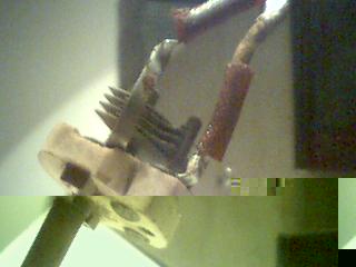
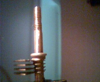
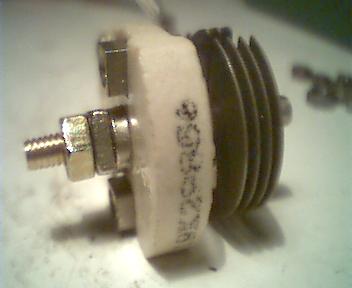
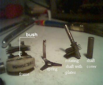
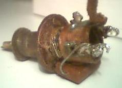
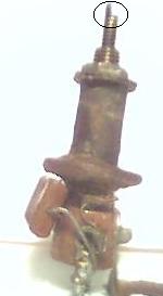
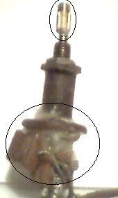
Started working on the BFO control variable capacitor (C57). It is in very bad conditions mainly for excessive wear and tear.Ā The bush where the shaft rotates in is so worn-out that the shaft has so much side clearance that the capÆs plates get in short. The shaft has also a significant end float.Ā Definitively the solution is to replace it, but willing to exhibit some mechanical ability, I tried to fix it and here is the story.
First I have dismounted it into its primitive components. The lack of mechanical strength between the main shaft and the shaft cover made the job very easy, but it also was the mainĀ reason for the shaft clearances. I noticed that, being the shaft forced inside,Ā the bush still allowed the shaft to stay in a correct position, keeping plates apart for the full rotation. So I focused on restoring the mechanical strength necessary to maintain the shaft in the correct position. Originally this strength is provided by the shaft cover. The idea was to replace the lost pressure force, threading the shaft and installĀ a nut and counter-nut play . Good job.
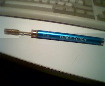
The problem is how to reinstall the shaft cover, now that the shaft diameter has been significantly reduced as a result of threadingģĀ OK soldering by mean of a handy pencil torch. Success!
The net result is a working variable capacitor, almost original, but with one problem: the rotation is not as smooth as it should be. The reason has to be looked for in the friction between the bush and the nut. In fact both the bush and the shaft cover (the components that were rubbing in the original set up) are made of brass, while the nut is made of steel. Lesson learned: steel and brass do not rub very well. I donÆt expect this solution to be the definitive one, but it gives me time to look for a better new replacement.
These are all the pics of the C72 restructuring
|
|
|
|
|
|
|
|
|
|
|
|

Go to the top of this page | Back to the Sx-28 page
3-10-2000
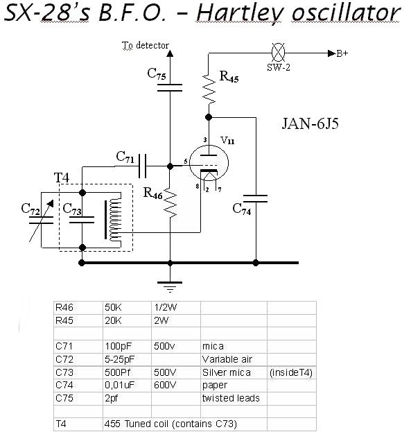
Started working on the BFO circuit. The tube found inside my unit was a 6SN7. It should have been a 6J5. A friend suggested somebody could have used one triode section of the 6SN7 as a replacement of the single 6J5 triode. BINGO!! The wiring was a real mess, absolutely not in line with the HalliÆs diagrams. So I decided to remove all the components attached to V11 and T4 and to rebuild the BFO from scratch. Just for the sake of history, here is the removal log:
- not original Geloso
electrolytic Cap (10uF, 30V) connected to: (-)T4-GND lead, (+)V11pin3
- 15Kohms resistor between
V11pin8 and V11pin3 (reads 16K)
- original SPRAGUE paper cap of
0.01 MFD 600V (ex C74) between (external foil) T4GND and V11pin5
- wire running from the
bandswitch wafer nearby to V11pin8 (unsoldered only from the tube socket
side)
- wire running from B4pin2(GND)
to V11pin8 (the previous wire was only used to bring GND to the switch ¢
needs double check later)
- 20K 10% 2W carbon (ex R45) from V11pin5 and B4pin1
- 50Kohm resistor (ex R46) from
V11pin8(GND) to V11pin4
- 250Kohm from V11pin3 and B4
pin2(GND)
By the way, by comparing the BFO diagram with the 6J5 and 6SN7 pin diagram, one can understand what some of the previous owners attempted to do. Maybe it was a good modģ but my interest now is to restore the radio as electrically original as possible. So I decided to reverse the mod.
Here is the empty V11 socket ready for rebuild according to the original Hallicrafters design.
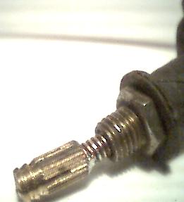
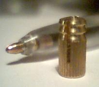
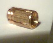
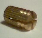
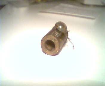
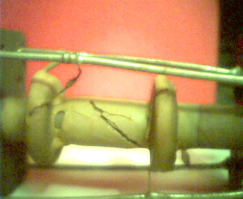
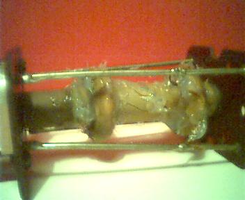
Wanted to check T4 internal conditions. Dismounted T4 loosening the two nuts between V11 and V12 sockets. Extracted the coil out of the shield by loosening the top nut. It looked like this; please note that the little threaded tuning shaft was damaged: one half of the top cut is missing. First of all I dripped some new wax (leaked from a candle) to fasten the coil and then I soldered a new top to the tuning shaft. I used a kind of brass plug (pic1, pic2, pic3) often used in house furnitureÆs (like bookshelves) to create metric threaded females (hole) to screw in metric screws in the wood.
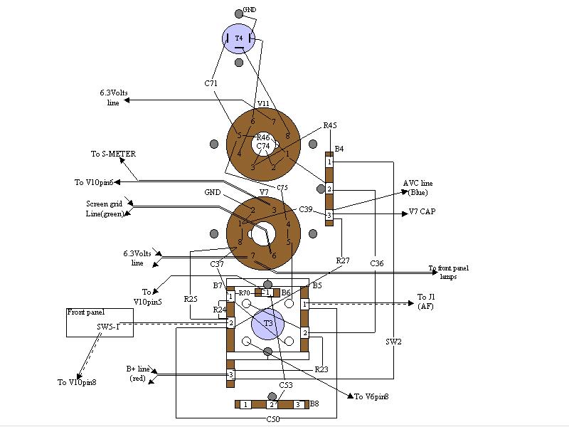
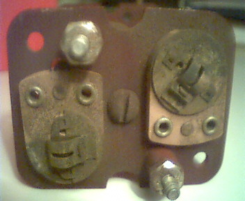
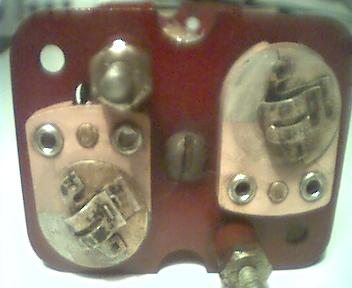
Before starting rebuilding the BFO, I started working on the detector/S-meter/IF-AVC stage, the driver for this choice being that V11 and V7 are so close one each other that it seems to be convenient simultaneously working on both.
Here is the components removal log:
- identified the three leads of
the screen grid divider: pin1&pin2 being the R32 leads and pin2 and
pin3 the R31 leads (in fact pin1 is connected to B+ line, pin2 to the
screen grid line and pin3 to GND ¢ as per diagram)
- to be able to work into the V10
(6H6) socket,
- dismounted R29, the s-meterÆs
zeroĀ setting potentiometer;
- disconnected S-Meter shunt
resistor (R28= 100 ohms) from one external lead of R29 to V10pin6 (unused
in 6H6);
- disconnected the non original
resistors coming out of the other external lead of R29 and directed to
the screen grid divider pin 1 (B+)
- disconnected one side of a
0.03uF 600V paper cap from V10pin1(GND) ; the other side is at T5
- to get better access to V7
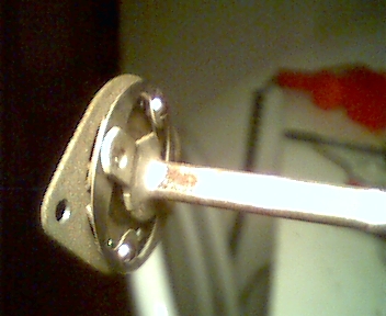
dismounted the ANT. TRIMMER shaft by unscrewing the two screws in the shaft joint close to C6
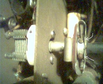
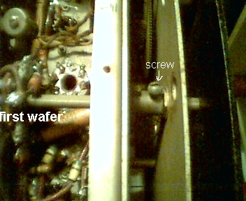
still to get better access, I also decided to get rid of the bandswitch shaftģ. But just withdrawing it without pulling it back enough to get it out from even the first wafer; to do this:
Ę loosened the screw on the brass cylinder installed on the shaft immediately behind the front counter panel
Ę unscrewed both screws fastening the shaft to the back of the chassisģ
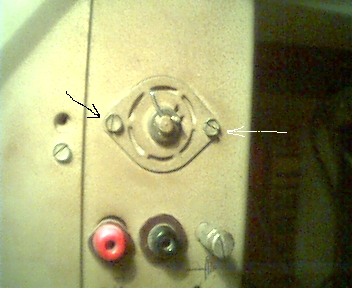
Ę then very carefully hit the shaft with a lite hammer, forcing it to move backward; SIMULTANEOUSLY addressing its back gear out from the hole in the back of the chassis. IÆve been very careful not to withdraw the shaft too much: the head has not to leave the first wafer: I donÆt know, at the moment, what can happen in the wafers in case the shaft is removed out from them.
I was afraid about the two little balls contained in the shaft gear and about loosing synchronization between the shaft rotation and the shaft detents. Fortunately the shaft gear remains intact and you donÆt occur in such a risks.
Go to the top of this page | Back to the Sx-28 page
15-11-2000
Had a strong look at the
ARRL Handbook about the AM detection process, AVC control voltage development
and noise limiting. Redesigned the detector/ANL/AVC diagram as it can be found
within my detector page for better
understanding.
10-12-2000
After days ofĀ hard work, I have removed all the components and logged my activity in the component sheet. Note the removal number: it represents the order by which IÆve removed the components ¢ to be used as a guideline when reinstalling new components. Also removed the V11 socket. The V7 socket is still in chassis as it has a lot of wires very difficult to get rid of. IÆll see.
I have also created the chassis diagram ; it is very useful! Hope this will help other people to save time in diving within the SX-28Æs chassis. It would be a good idea to do the same job for the power supply and the LF amplifierģ IÆll see..
Go to the top of this page | Back to the Sx-28 page
25,26/12/2000 (ChristmasÆs
days)
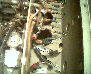
Finally removed V7 socket as well as V11. Cleaned up wires. Wires repainted using PAPER-MATE permanent markers.Ā Everything is ready to start reconstruction.
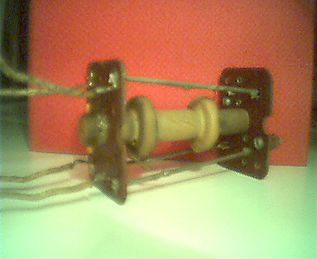
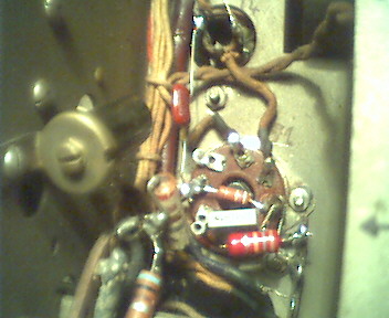
Dismounted T3. As it looked very ōdryö with some flaws in the protective material and trim caps oxidized and dirty. ĀI filled it with some silicon to protect and secure the coils. Trim cap polished with G-20 to deoxidize and clean them up.
To start rebuilding the BFO I designed a possible layout for the components as, due to the heavy tampering with suffered by my unit, I donÆt have a reference for it. Posted a request of help on the hallicrafters@qth.net mailing list.
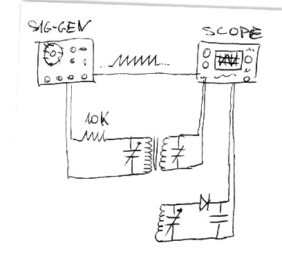
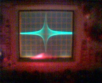
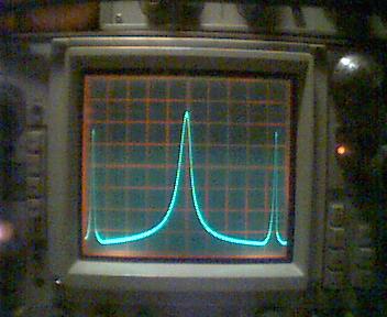
Due to this waiting status, I decided to play a little with T3 and my signal generator and scope. Connecting it like this, feeding the primary coil with a signal sweeping between about 400KHz and 500KHz. I have got this nice behavior (values are indicative only asĀ - incredible to say ¢ I miss a frequency counter! I only used my Kenwood ts-430s as a raw selective voltmeter tuned to 455KHz. Furthermore my sig-gen is not very suited to sweep between frequencies: it only allows for sweeps in a range expressed by a ratio of the main frequencyģ. Modifying the connection like sketched in the bottom part of the diagram, that is adding a ōdetectorö to the circuit, I have got this nicer picture as expected (the two side peaks are just the noise produced by sig-gen at the end of a sweep sequence..). Trimming the primaryÆs trim-cap the curve improved a little in its shape getting narrower. Trimming the secondaryÆs the effect was to move the peak around the frequency range.
By the way I have got the same results either with direct sync between the sig-gen and the scope working in X-Y mode, and with the scope in normal mode and adjusting it to stay in sync with the sweeps.
Definitively a good time for my Christmas vacations!
Go to the top of this page | Back to the Sx-28 page
10-1-2001
Rebuilt the BFO circuit and now ready to fire my rig up again (itÆs a long time since it received powerģ).
Surprise: some arching happened within one of the 6V6ģ so I have immediately shut down power, pulled out all theĀ tubes and started investigating the reason for this strange behavior.Ā Giving power again with all the tubes out but the rectifier(5Z3) I measured an unreasonable high potential in the B+ line (360V!). My memory served me well in remembering that back in march, at the time I gave it power to test the LF amp, I had some difficulty in getting stable volt measurements.
My suspects go against the R31-R32 voltage divider.
In the mean time I was able to test the BFO osc. That seems working properly (sine wave at 455KHz almost stable in time ģ).
Go to the top of this page | Back to the Sx-28 page
10-2-2001
Dismounted and tested the screen grid voltage divider. It measures ok most of the times, but it seems to be instable. Temporarily substituted with two wire resistors; this way I got a reasonable stability in voltages in the rig. Still it remains to understand what really happened when I measuredĀ B+ = 360Volts and the 6v6s arched..
I have also noticed that the manual copy IÆve got from Mr.Roger Engle is reporting wrong voltage values for B+ as well as for the screen grid lineģIÆve checked it against all the diagrams found at bama.stc.edu Ā28, 28a, 28Mil, 28aMil. They all report for B+ = 280V, screen grid line = 100V while RogerÆs reprint states for B+ = 250V and screen grid = 120v. May be one day IÆll ask him why.
Go to the top of this page | Back to the Sx-28 page
Between March and September
2001
No much time dedicated to the rig. Repaired one friendÆs television, a VCR, an HI-FI amplifier. IÆve read a lot aboutĀ tubes and tube amplifiers and written down the technical part of the LF power amplifier page.
I have also read something on HTML trying to fix some site problem. Mirrored the site at www.qth.net/iw1dhi. Changed the SX-28 home page introducing the block diagram as a graphical index to the rest of the sx-28 pages.
Go to the top of this page | Back to the Sx-28 page
September 11 ¢ 2001 :Ā
one of the worst happening for humanity.
2/10/2001
Detector and
LF-ANL reconstructed. The choice was to take advantage of the smaller size of
modern components to get to chassis ground for by-passes in the closest
available points, thus violating the original layout. If you are a sensible
person, donÆt look at this picture! The
chassis diagram and the component list with the removal sequential number were
of invaluable help to make the job easier. Hope it will help somebody else as
well.
|
Top of page | Back
to the Sx-28 page |
|
Last update: 05/01/02
15.28.00 |
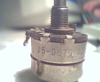
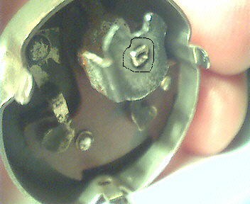
4/10/2001
SW5-1, the
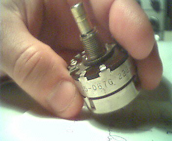
ANL control (R53) operated switch, resulted inoperative. The potentiometer shaft
is ok, the rotation is ok, but at the end of the rotation there is no switch
click. It just become tougher.
Start the
R53 restoring log. Dismounted form front panel and the disconnected. It is original. The potentiometer parts look
ok but some electric noise is noticeable with the VOM while turning the shaft:
need cleaning.
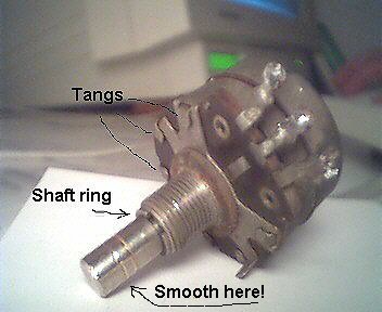
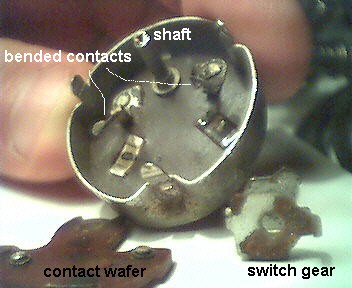
First of
all I have removed the half ring keeping the shaft in its position and then
heaved up all the small tangs that keep the
frame together. Operating veeeery carefully, I have then got all the components separated. It was a good idea
to smooth the visible part of the shaft before proceeding by mean of some emery-paper.
During the extraction operation, it has to go through the bush where there is
no much space left while the shaft was ruined by the knob screw.
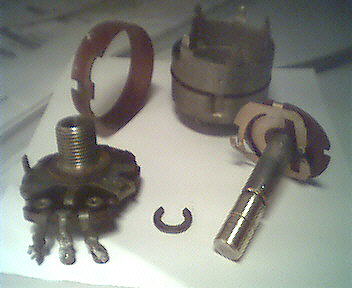
The
dismounting job is not complete yet: the switch frame has to be dismounted as
well. By the way, the switch gear is completely locked: it is easy to
understand why it didnÆt work. Switch spring dismounted with no difficulty.
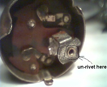
Switch gear shaft un-rivetted ; look at the its head before and after
the treatment.Ā Gently pulled out the
gear and then, after having bended the contacts tangs carefully,Ā the switch wafer containing the copper
contacts was also out. While bending the contact tang, keep in mind that you
have to bend them back to their original shape later on. Not an easy task. Here are all the components.
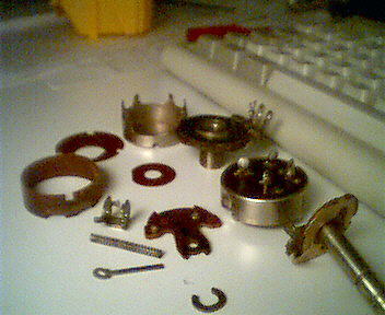
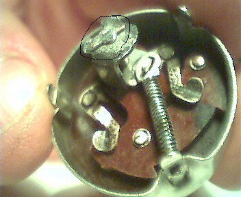
After an
overall and deep cleaning, here is the switch
gear restored. Please note that to lock the gear into the shaft I soldered
a piece of copper wire at the top, as a substitution of the riveting
arrangement. I have also cleaned up all the potentiometer parts and remounted everything
with no major problems. R53 restored : the
switch clicks correctly and works electrically, the potentiometer changes
resistance smoothly.
One
question remains to be answered: how long will it last?
|
|
Last update: 05/01/02
15.28.00 |
10/11/2001
To proceed
rebuilding the S-Meter circuitry, I needed to clean the V10 area at least for the
relevant components.
It has been
an easy task that I donÆt log it in detail.
At the end
the S-Meter circuitry is rebuilt.
I am ready
to fire the rig again to test: detector, ANL, S-Meter.
At startup
everything went smoothly (non shorts, no fires, no ticks or click,..) but , as
it happened the last time I fired the rig up, voltages are all out of specs,
exceeding the correct values ofĀ a
20-25%.
Before
getting some arching again within the 6V6Æs, I decided to face this problem
having it solved before getting further.
This
activity brought me to the construction of the BAPS
(Boatanchor AC Power Supply), described in a dedicated page of this site.
|
|
Last update: 05/01/02
15.28.00 |
10/12/2001
With the
extra voltage problem solved by mean of the BAPS, I am now ready to turn the
radio on again.
Everything is
now really ok, including most of the voltages. . (screen grids line voltage is
still too high(140V) , but that can be due to the missing tubes.. IÆll see).
First of
all I wanted to test the S-Meter stuff. The meter itself worked fine with a
small rectified sine signal, exposing a good needle movement covering the
entire range smoothly.
The DC
amplifier (Penthode section of V7) worked well using the glass type 6B8 I have;
control grid bias is ¢0,7V andĀ it was
easy to ōzeroö the meter by mean of R 29. Injecting a variable signal between 3
and 12Volts the meter moved full range.
|
|
Last update: 05/01/02
15.28.00 |
20/12/2001
To test the
detector circuitry I used my RF Generator to inject a 455KHz signal AM
modulated at 1KHz into T3Æs primary windings, by mean of a 1Kohms resistor; I
was able to ear the 1KHz whistle out of the speaker but it was at very low
level. The S-Meter moved very few. AVC voltage developed by the AVC network was
not exceeding 1,5V Volts. The signal injected that way was insufficient to get
a good test. So before proceeding I decided to reconstruct the last IF
amplifier. This way I should be able to inject the signal in the control grid
of V6 to get a output signal wide enough to successfully test the circuits I
have just restored.
|
|
Last update: 05/01/02
15.28.00 |
3/2002
Started working on 1st IF amplifier. Removed some components and drawn some layout.
Project on-hold due to heavy duties at work.
|
|
Last update: 05/01/02
15.28.00 |
| Top of Page - Back to the Sx-28 home | Last update: 05/01/02
15.28.00 |