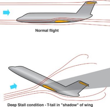
Deep stall is a dangerous condition that effects certain aircraft designs, notably those with a T-tail configuration. In these designs, the turbulent wake of a stalled main wing 'blanks' the horizontal stabilizer, rendering the elevators ineffective and preventing the aircraft from recovering from the stall.
Although effects similar to deep stall had been known to occur on many aircraft designs, the name first came into widespread use after a deep stall caused the prototype BAC 1-11 to crash, killing its crew. This led to changes to the aircraft, including the installation of a stick shaker in order to clearly warn the pilot of the problem before it occurred. Stick shakers are now a part of all commercial airliners. Nevertheless the problem continues to periodically haunt new designs, in the 1980s a prototype of the latest model of the Canadair Challenger business jet entered deep stall during testing, killing one of the test pilots who was unable to jump from the plane in time.
Stalling of Swept Wings.
When a swept-wing travels at high speed, the airflow has little time to react and simply flows over the wing. However at lower speeds there is more time for motion and a strong streamline, and with the front of the wing angled, some of the air is pushed to the side towards the wing tip. At the wing root, by the fuselage, this has little noticable effect, but as you move towards the tip the airflow is pushed sidewise not only by the wing, but the sidewise moving air beside it. By the time you reach the tip the airflow is moving along the wing instead of over it, a problem known as spanwise flow.
The problem with spanwise flow is that the lift of the wing is generated by the airflow over it from front to rear. As an increasing amount travels spanwise, the amount flowing front to rear is reduced, leading to a loss of lift. Normally this is not much of a problem, but as the plane slows for landing the tips can actually drop below the stall point even at speeds where stalls should not occur.
The spanwise flow along the wing that results from the sweepback causes the boundary layer on the outboard sections of the wing to thicken, as compared with an unswept wing. The thicker boundary layer near the tip of the wing causes the maximum lift capability of these sections to be reduced, as compared with the two-dimensional value.
Thus, for untwisted wings equipped with airfoil sections having the same maximum lift coefficients, the initial wing stall would be expected to occur near the wingtip.
When this happens the tip stalls, and since the tip is swept to the rear, the net lift moves forward.
Further increases in angle of attack would cause an inward progression of the stall. A loss in load near the wingtip may, depending on the sweep angle, taper ratio, and aspect ratio, cause a forward shift in the wing aerodynamic center.
This causes the plane to pitch up, leading to more of the wing stalling, leading to more pitch up, and so on.
This behavior is in contrast with that of a straight-wing aircraft that has inherent stability at the stall and pitches down to a lower angle of attack and into an unstalled and fully controllable flight condition.
This problem came to become known as Sabre dance in reference to the number of North American F-86 Sabres that crashed on landing as a result.
Pitch-up at the stall is considered to be a highly undesirable flight characteristic. In the development of a new aircraft, much attention is given to wing design and configuration arrangement to avoid pitch-up. Electromechanical devices must be used in some cases to provide acceptable flight characteristics at high angles of attack.
The solution to this problem took on many forms. One was the addition of a strip of metal known as a wing fence on the upper surface of the wing to redirect the flow to the rear (see the MiG-15 as an example), another closely related design was to add a dogtooth notch to the leading edge (Avro Arrow). Other designs took a more radical approach, including the XF-91 Thunderceptor's wing that grew thicker towards the tip to provide more lift there, and the British-favoured compound sweep or scimitar wing that reduced the sweep along the span, used on their V Bombers.
Modern solutions to the problem no longer require "custom" designs such as these, but are taken as a whole with the need for shorter takeoff and landing than the early large jets. The addition of leading edge slats and large compound flaps to the wings have largely resolved the issue. On fighter designs, the addition of leading edge extensions, included for high manoeuverability, also serve to add lift during landing and reduce the problem.
The Deep Stall.
The discussion so far has dealt only with wing-alone stalling behavior. The stalling and subsequent pitching characteristics of the aircraft, however, are highly dependent upon the details of the aircraft configuration. The longitudinal and vertical position of the horizontal tail with respect to the wing is particularly important.
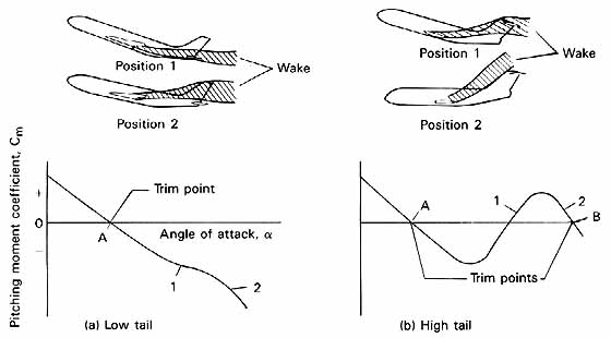
Some indication of the flow phenomena involved in the wing-tail relationship, however, may be gained from the figure below.
At the top left side of the figure is an aircraft configuration on which the horizontal tail is slightly above or below the chord plane of the wing. At position I the wing is just beginning to stall and the tail is immersed in the wake.
The hypothetical pitching-moment curve in the lower portion of the figure shows that a reduction in stability is beginning at point 1.
At position 2 the aircraft is at a higher angle of attack, and the wake from the wing passes above the chord plane of the tail. The contribution of the tail to the positive stability of the aircraft is therefore increased at point 2, as compared with point 1, because the tail is operating in a flow field characterized by smaller downwash angles and higher dynamic pressure. The pitching-moment curve shown at the bottom of the figure shows the higher stability of the aircraft at position 2 and indicates that there is no real pitch-up, although a small reduction in stability occurs at the stall. The pitching-moment curve for the aircraft configuration with the tail mounted in the low position would be considered acceptable, although not as desirable as that of a design that showed no reduction in stability at the stall.
An aircraft configuration in which the horizontal tail is mounted high above the chord plane of the wing is shown at the right side of the figure. A greater portion of the wing is stalled on this type of configuration, as compared with the design with the low tail, before the tail encounters the stalled wake. The wake is therefore broader in width and of a lower dynamic pressure for the high tail position. Position I in the upper part of the figure shows the high tail immersed in the wide, low-energy wake. The hypothetical pitching-moment curve at the bottom of the figure indicates the large reduction in stability that accompanies an increase in angle of attack as the tail passes through the wake. Following emergence of the tail from the wake, the aircraft again becomes stable and with further increases in angle of attack reaches a second trim point as indicated by point B on the pitching-moment curve. If the longitudinal control surfaces are in the full nose-down position and the pitching-moment curve appears as depicted in the figure, no recovery is possible if the aircraft is allowed to reach the second trim point B.
Although fighter aircraft have in the past been configured with a high tail position, the requirement for fighter-type aircraft to engage in high-g maneuvers at high-subsonic and transonic speeds makes the use of a low tail position very desirable to avoid the possibility of pitch-up into an uncontrolled flight condition. The consequences of such an uncontrolled maneuver in a combat situation can well be imagined.
Since high-g maneuvers are not required on large transport aircraft, acceptable pitching-moment characteristics can usually be obtained with a high tail position by careful tailoring of the wing and tail designs and their relationships to each other. For configurations that employ engines mounted on the aft portion of the fuselage, careful attention must be given to exact placement of these engines since the wake from the engine nacelles at high angles of attack may combine with that of the wing and contribute to the loss in effectiveness of the horizontal tail. In some cases, acceptable pitching-moment characteristics cannot be achieved by aerodynamic refinements alone. In these cases, mechanical devices such as stick shakers or stick pushers, sometimes both, are employed to prevent the aircraft from entering a potentially dangerous angle-of-attack region. A stick shaker is a mechanical device that causes the control column to vibrate violently as the aircraft approaches a restricted angle-of-attack range. The vibration is intended to alert the pilot to an approaching stall and to make him take corrective action to reduce the angle of attack. A stick pusher causes the control column to be pushed forward mechanically with a considerable force, perhaps 100 pounds, as the critical angle-of-attack range is approached. Sometimes the devices are employed together, in which case, the stick shaker is first activated, and if the pilot ignores the warning and permits the aircraft to continue pitching to a higher angle of attack, the stick pusher comes into action. Both the stick pusher and the stick shaker are activated by signals from instruments that sense parameters such as angle of attack, rate of change of angle of attack, attitude and its rate of change, or some combination of these parameters.
Acknowledgements:
Text and images of this page are taken from the following websites:
This is a free site, that makes itself know mostly thanks to the echoing of its users; also you can contribute: signal this site to your interested friends. Thank you very much indeed.