First of all, you need to be experienced in soldering. If this your first attempt with a soldering iron, please
don't go on. Stop here also if this is your second one! The minimum required is a normal iron soldering, with
all the usual stuff, soldering paste etc. The iron should be enough little to do very little soldering. Please note
that a specific stuff for SMD is really welcome. You don't need anything more than this, better if you have time and
a calm hand. Ah, of course you need a BlizzardPPC :-) I tried successfully to overclock 200 and 240Mhz boards, I didn't
look at 160 and 175 ones, but I believe that nothing changes (you just have to check the speed of your crystal and calculate the
resulting speeds).
Overview
First, a little bit of theory on overclocking. The speed of the processor is strictly dipended from the bus speed. The bus
speed is given by a crystal. For 240Mhz boards, it's a 60Mhz one, while for 200Mhz ones it is a 66.666Mhz one. To get the
processor clock, you have to set up the clock multiplier as desired. For example, 240Mhz have a factory setting of 4x
(60*4=240) multiplier, while 200Mhz ones use a factor of 3 (3*66.666=200). I still have not tried to put a 66Mhz crystal on
240Mhz BlizzardPPCs, as soon as I try I will write the results. So what we are going to do is to increase the multiplier
of the clock to overclock the CPU. For example, switching to 5x with a 60Mhz bus will push the CPU to work at 300Mhz!
On old PCs, you can overclock the processor simply changing some jumpers, or even directly from the BIOS. On the Blizzard, you have to select manually
the multiplier, changing with the soldering iron the position of 4 resistors. Note that overclocking the CPU means that
it wil run hotter than before, so adding a heat sink and a fan on the ppc, over the Phase5 heat sink is a good idea.
But I am running my 240Mhz BPPC at 270Mhz for hours, and the heat gain is irrilevant. I tried to push my board up to 300Mhz
but at that speed the system is unstable with PPC applications, I think because the memory working still at 60Mhz can't handle
such speeds. There are then two ways to overclock BPPCs: change the multiplier, or get an higher bus speed, that will increase
also the CPU frequency. Of course the second is the best, as will result in better performance not for the CPU only, but also for
the memory access, and since BPPC has a 32bit memory access, it is very welcome.
The multiplier way
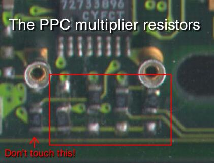
The first thing you have to do is to locate the multiplier. The multiplier itself is under the PPC crystal, but its settings can be
changed with the little SMD resistors just near it. See this scheme to find them.
A magnifying lens will surely be useful. As you see, there are 5 little resistors. The first on the left is not used
now, while the other four control the PPL_CFG signals, from 0 to 3. The resistors can be in 2 different
positions, 1 or 0. Te resistor is on 1 when is near the crystal, on 0 when is near the edge of the card. In the
scheme, the code used is 0111 (don't count the first one). This is the specific for 4.5x multiplier. You can guess
that if we know the settings codes of the multiplier, we can change it as we want. Where to find them? Simple, on Motorola
WWW site. You should download the manuals for the 603e in the pid7 version. Luckly I already did this for you, so here are the codes:
So what you have to do is to solder the resistor at the multiplier you want to use. If you have a 200Mhz Blizzard you
may safely bring it up to 266Mhz simply switching from 3x (factory setting) to 4x. If you have a 240Mhz Blizzard like me
you can pull it up to 270Mhz switching from 4x to 4.5x. I tried with no luck the 5x setting. PPCTool recognizes the board as
a 300Mhz one, but PPC applications refuse to run. If you want you can try to change the 60Mhz crystal with a 66Mhz one,
getting 266Mhz without messing with the resistors. Try, if you can find the oscillators, different speeds, and choose the
one you find better.
The oscillator way
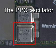
To change the bus speed you have to change the crystal with a faster one, like a 66, 66.666 or up to 70Mhz. You need then to take off the old
oscillator. The PPC one is near the edge of the board, see the picture for a better explanation. Be MUCH careful, under the crystal there's a chip,
don't touch it or you will make you card unusable. You can now plug the new faster crystal in the space left by the other. If you want to change
faster, mount a little socket. This will help you avoiding many problems with soldering up and down. Beware! If your memory isn't of good
quality, you may need, after the overclock, to activate from the BPPC bootmenu the PPC precharges or the PPC preloads.
Problems
Actually I have no problems at all. I had much problems to solder the resistors in the right position. To put them in the
"1" position, you have literally to solder UNDER the crystal, as the contact is slighty covered by it. This means that you need
a clear desk with a direct light on it, and a very small soldering iron or you won't be able to do it. If you find really
too difficult to reach the contacts, you can remove the crystal (it has only 4 pins), perform the changes, and remount it.
Initially I tought that SCSI suffered from problems, because at the first boot I got "unable to open blizzppc.device unit 2"
when starting the cd0, but after a check i found that when removing the card the connector wasn't well plugged :-) So be
sure that overclocking the PPC doesn't affect the SCSI controller (as far as i know, it's controlled by the 50Mhz crystal
Look in the SCSI section of this site to discover how to get better performances from you SCSI adapter.